RF Mini: adding RF to the Arduino Pro Mini
Introduction
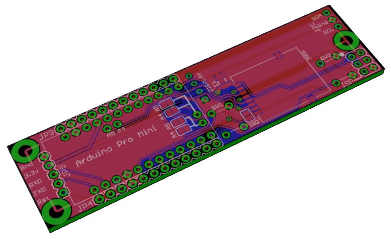
RF Mini is a unpopulated, breadboard-friendly, PCB which adds RF to an Arduino Pro Mini using an Ebyte E01-ML01SP4 module with NRF24L01 radio. RF-Mini also adds a standard 6-way ISP header for programming the Pro Mini bootloader.
Components required to complete RF Mini
In addition to the Pro Mini and RF module mounting holes are provided for:
- 6-way ISP header - so the Pro Mini bootloader can be reprogrammed.
Programming may be done with an AVRgpp, AVR ISP mkII, AVR ICE, USBASP or Arduino UNO.
- 3-way I2C header - SDA (A4),SCL (A5) and Ground.
- 5-way Support Module header - Gnd, 3.3V, RXD, TXD, Reset see below.
- Two buttons.
- 128 x 32 I2C OLED display.

The links below provide sources for individual components:
- 3.3V Pro Mini
- E01-ML01SP4 RF module
- Stick-on IPEX antenna
- or External "rubber duck" SMA antenna
- 128 x 32 I2C OLED display
- Two button switches.
- 59 vertical 2.54mm male headers (usually sold in 40 pin lengths)
- 5-way right angle male header (sold in different lengths)
- A surface mount (SMD) 10uF capacitor (6.3V to 50V) in 1206 size (3.2mm x 1.6mm). This is an example.
Never soldered before?
Try this video then invest in one of these or try a Google search for "digital soldering iron".
Collin grows on you over time and he has other excellent videos:
The E01-ML01SP4 module has an IPEX socket for a stick-on or "rubber duck" SMA external antenna which extends the range of the NRF24L01 up to a claimed 2km (line-of-sight).
Sample code is provided to demonstrate use of the OLED and buttons as a menu-driven human interface.
3.3V
The E01-ML01SP4 is a 3.3V device so RF Mini must be fitted with a 3.3V Pro Mini.
RF Mini must be provided with 3.3V power, not 5V. The RF Mini Support Module (see below) provides 3.3V from a 3.7V Li Ion battery and ensures that all signal levels are correct.
PCB layout
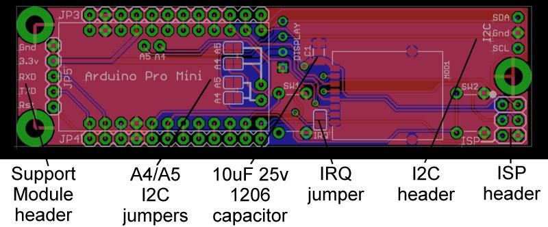
Different Pro Minis have the I2C pins (A4 and A5) at different locations so pads are provided for solder bridging to bring the I2C lines (A4 = SDA. A5 = SCK) out for the OLED and the I2C header.
Important note: the correct pair of A4/A5 pads must be bridged before soldering the Pro Mini in place.
The IRQ line from the E01-ML01SP4/NRF24L01 is not used in many application but pads are provided to link it to Pro Mini pin 8 (PB0) if required.
RF Mini has two rows of additional headers underneath to enable it to fit to a breadboard.
The drawing shows RF Mini on a half size (400 point) breadboard.

RF Mini Support Module
The Support Module enables RF Mini to operate stand-alone with 3.3V power from a rechargeable battery. It also adds a USB connection for charging and for programming from a PC via the Arduino IDE.
Once components are soldered to the Support Module a 14250 3.7V Li Ion battery is required to make it ready for use.

Connection to the RF Mini is via a 5-way header.
Why use a 5-way header?
The 6-way end connector on the Pro Mini carries VCC, Gnd, TXD, RXD, DTR and one other. Pro Minis from different places (SparkFun, Adafruit, China) have these signals on different pins - there is no "standard".
RF Mini leaves the 6-way end connector alone and uses its own 5-way connector (Gnd, 3.3v, RXD, TXD and Rst) with signals going directly to the correct pins on the Pro Mini PCB. This makes it compatible with all Pro Minis, no matter where from.

Pin usage
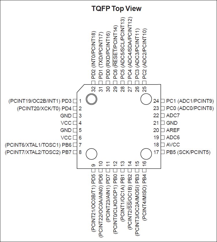
The Pro Mini uses an ATmega328P chip - the datasheet may be downloaded from here.
RF Mini Pin usage
Pin usage is shown in these definitions from the sample code.
Note
The code refers to an LED and speaker/amplifier that are not on the RF Mini PCB but they can be added when the board is plugged into a breadboard.
// *********************************************************************************************
// Processor line usage - 32 pin ATmega328P.  32KB flash, 2KB SRAM, 1KB EEPROM
// nRF24L01 support:  https://github.com/nRF24/RF24
// See rf_mini.h for processor port mapping to Arduino pin numbers
// **************************************************************************************************

#define RXD        PIN_PD0     // IDE pin  0 - goes to TX of CH330N on RF MINI Support Module
#define TXD        PIN_PD1     // IDE pin  1 - goes to RX of CH330N on RF MINI Support Module
#define button1    PIN_PD2     // IDE pin  2 - button one
#define button2    PIN_PD3     // IDE pin  3 - button two
#define LEDPin     PIN_PD4     // IDE pin  4 - LED                **** NOT PROVIDED WITH RF MINI ****
#define speaker    PIN_PD5     // IDE pin  5 - speaker/amplifier  **** NOT PROVIDED WITH RF MINI ****
#define unused3    PIN_PD6     // IDE pin  6
#define unused4    PIN_PD7     // IDE pin  7

#define RF_CE      PIN_PB0     // IDE pin  8 - CE  pin on E01-ML01SP4/NRF24L01
#define RF_IRQ     PIN_PB1     // IDE pin  9 = IRQ pin on E01-ML01SP4/NRF24L01 - if the PCB jumper is bridged
#define RF_CSN     PIN_PB2     // IDE pin 10 - CSN pin on E01-ML01SP4/NRF24L01
#define MOSI       PIN_PB3     // IDE pin 11 - SPI
#define MISO       PIN_PB4     // IDE pin 12 - SPI
#define SCK        PIN_PB5     // IDE pin 13 - SPI

#define unused6    PIN_PC0     // IDE pin A0
#define unused7    PIN_PC1     // IDE pin A1
#define unused8    PIN_PC2     // IDE pin A2
#define unused9    PIN_PC3     // IDE pin A3
#define SDA        PIN_PC4     // IDE pin A4 - I2C
#define SCL        PIN_PC5     // IDE pin A5 - I2C
Sample code and resources
Sample code will be available for download from this web site.
The sample code is provided "as is" with no support. It provides examples of what can be done with RF Mini.